

OPTOSEIS™ PRM
Fiber Optic Permanent Reservoir Monitoring



PRODUCT DETAILS
Fiber Optic Permanent Reservoir Monitoring (PRM) provides the best platform for accurate and detailed measurements of changes to the reservoir, enabling better modeling of dynamic reservoir behavior and increased oil and gas production.
Features
- 3000m depth capability
- Fiber count: 84 fibers
- Designed for simplified sensor integration
A PASSIVE FIBER OPTIC SUBSEA SYSTEM
Installing seismic sensors permanently to the sea floor maximizes seismic signal recovery from the production affected reservoir zone, allowing for much smaller 4D (time-lapse) changes to be detected. Geospace’s Optoseis sensors have been optimized for permanent installation with sensing and recording technology that provides superior dynamic range and the broadest seismic bandwidth.
Utilizing optical fiber technology eliminates the need for electrical components in the water, making the system more reliable, safer, and easier to deploy than traditional electric seabed systems.
Optoseis offers a lower noise floor, with reduced crosstalk and a higher dynamic range than other fiber optical systems, even for very high channel counts. Geospace provides a full turnkey solution for your life of field seismic needs so you can enjoy industry leading data quality for the next 25 years.
TOPSIDE EQUIPMENT
The topside and subsea portions of the OptoSeis system are connected through a Riser Umbilical. This Riser cable can be retrofitted as a dedicated stand-alone trunk line or integrated as an optical core within a larger electro-hydraulic production umbilical for cost savings in new field developments. Electrical power, HVAC, optical deck cables, and IEC zone-rated junction boxes can also leverage existing platform capacity or be provided with the OptoSeis topside system for independent operation. The sophisticated OptoSeis optoelectronics collect, demultiplex, and perform high speed analog/digital conversion of returned seismic signals. Designed for low power consumption and minimal footprint, a containerized system can accommodate 50,000 channels with integrated HVAC and work stations within a 20ft ISO container. Scalable up to one million channels, OptoSeis “rack-and-stack” packaging of optoelectronics is easily adaptable to integrated control rooms, turrets and containers. This truly flexible solution is also network ready for remote operation and live data streaming to shore.
ARRAY CABLE AND SUBSEA EQUIPMENT SENSORS
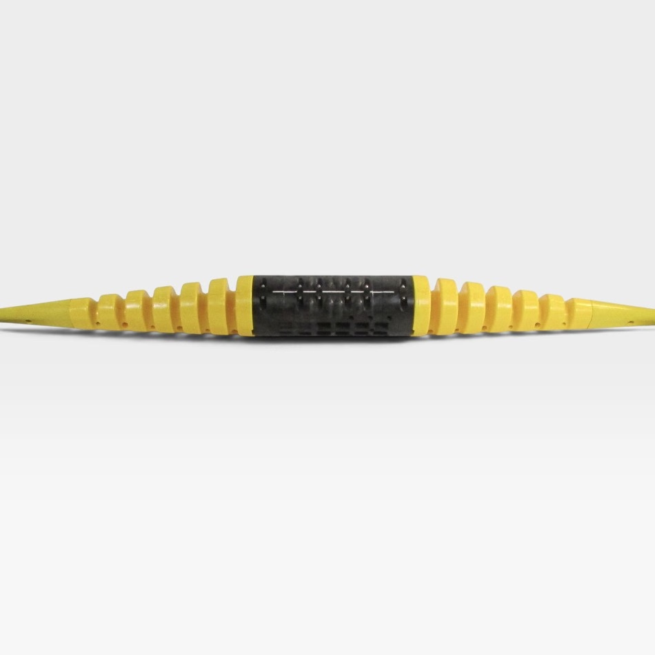
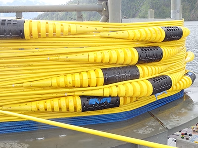
Leveraging high channel count single mode fiber, this lightweight cable design has a diameter of just 20.7mm yet tensile strength to support deployments in 3000m water depths with a high safety factor. The hybrid design of easily accessible pressure-balanced tubes and redundantly sealed atmospheric through tubes accommodates varying sensor spacing and individual array lengths up to 70km. When necessary, this durable cable integrates with a variety of field-proven flowline crossing accessories for even more abrasion and crush resistance.
OptoSeis multicomponent sensors recover more seismic energy by leveraging their high dynamic range, superior fidelity, low crosstalk, and pressure-balanced design. With a system noise floor well below offshore environments, the OptoSeis system is able to provide superior data quality.
Geospace optical sensors configured as Michelson interferometers observe a proportional phase shift in the coherent light when sensing seismic signals. Three orthogonally mounted accelerometers are collocated with a hydrophone within each OptoSeis receiver station. All four components are completely passive fiber optic devices requiring no electrical power and are fully pressure-balanced for unparalleled depth capability.
System Specifications
|
System Size/Capacity
|
112 – 250,000 4C Stations
|
|
Measurement System
|
Frequency and Wavelength-Division Multiplexed Michelson Interferometer
|
|
Telemetry
|
WDM/FDM Bi-Directional or Uni-Directional
|
|
Topside Integration
|
Fully Integrated with Production Control Systems or Containerized(Standalone IEC-certified module with self-contained UPS, HVAC, workspace)
|
|
Sample Interval
|
Field Programmable: 1/4ms – 8ms
|
|
System Power (assuming 230VAC supply, excludes UPS & HVAC)
|
2000 4C Receivers = 14 kW, 3000 4C Receivers = 17.5 kW, 4000 4C Receivers =21.5 kW
|
SUBSEA ARRAY SPECIFICATIONS
|
Maximum water depth
|
3000 m (qualification testing performed to 4500 m)
|
|
Operating temperature
|
-20°C to 60°C (storage/functionally responsive), 0°C to 33°C (full operational use)
|
|
Maximum lead-in distance
|
50 km without amplification
|
|
In-line Sensor Spacing
|
12.5 – 250 m
|
|
Maximum array cable length (receivers @ 50m)
|
28 km (can be tailored longer if necessary)
|
|
Maximum number of array cables per hub/backbone
|
12 (can be tailored higher if necessary)
|
|
Array cable weight in air
|
1050 kg/km
|
|
Array cable weight in water
|
700 kg/km
|
|
Operational load
|
93.5 kN
|
|
Breaking load
|
171 kN
|
|
Cable OD
|
21.7 mm
|
|
Burial
|
Jetted, trenched, rock dump, and non-buried applications supported
|
|
Receiver Unit Length
|
339 mm rigid length (1520 mm including bending strain relief)
|
|
Receiver Unit Diameter
|
160 mm
|
|
Receiver Unit Weight in air
|
19 kg (heavy/non-jetted variant 23 kg)
|
|
Receiver Unit Weight in Water
|
4.5 kg (heavy/non-jetted variant 8.3 kg)
|
|
Minimum Bend Radius (under max operational load)
|
1.25 m
|
HYDROPHONE SPECIFICATIONS
| Type | Pressure-balanced Fiber Optic Interferometric Hydrophone |
| Sensitivity Versus Depth | ≤0.5 dB over operational depth range |
| Maximum Input Signal | 35 kPa RMS at 31.25 Hz |
| Input-referred Noise | 2 mPa RMS at 2 ms output sample rate |
ACCELEROMETER SPECIFICATIONS
|
Type
|
Pressure-balanced Fiberoptic Interferometric Accelerometer
|
|
Maximum Input Signal
|
42 m/s2 RMS at 31.25 Hz
|
|
Input-referred Noise
|
3 µm/s2 RMS at 2 ms output sample rate
|
|
Fixture Layout
|
Triaxis Orthogonal < +/- 0.5°
|
|
Crosstalk Isolation
|
>80 dB
|

